

BitHound - An FPGA Based Logic Analyzer
![]()
Introduction
This page documents the outcome of the "Gruppenarbeit" (group work, simple academic thesis at ETH Zurich) realized by Mario Mauerer and Lukas Schrittwieser in fall term 2010.
The result of our work is an FPGA based logic analyzer. The design is based on the older SUMP logic analyzer which can be found at http://www.sump.org/projects/analyzer/.
We've also participated with this Logic Analyzer at the "Digilent Design Contest 2011" and won the first price in the global finals. :-) (Atlys BitHound V2.0 resulted from the participation at that contest)
This Logic Analyzer is able to sample 32 digital channels. The data will be transferred to a PC where a Java-based client will display them.
The digital signals from the device under test are transferred via an Interface-Board that provides overvoltage protection and level shifting to the FPGA which pushes them into a memory. The data is then transferred via ethernet to the client software running on a PC which displays the waveforms.
The key features of the BitHound are:
- 16 channels at 400MHz sampling rate
- 32 channels at 200MHz sampling rate
- 128MByte sample memory
- 100MBit/s Ethernet interface for fast data transfer
- Based on a low cost Spartan-6 board from Digilent (an older version of the BitHound is available for a Xilinx board)
- Interface Board with overvoltage-protection
- Capable to analyze circuits that range from 2.5V to 5.5V
- Java GUI for data viewing and analysis (taken and improved from SUMP logic analyzer)
- Fully open source, many cores from opencores.org using the wishbone-interface
If there are any problems, remarks, recommendations or comments about this project, the sources or anything related, please contact: lukas@bastli.ethz.ch or mario@bastli.ethz.ch.
There are two versions of our BitHound. One for the "ATLYS Spartan-6" FPGA-Board from Digilent and one for the "Xilinx SP601" FPGA-Board. The Version for the SP601 from Xilinx is the direct outcome of the "Gruppenarbeit" at ETH Zurich and is no further developed by us.
The version for the Digilent ATLYS-Board ist the outcome of the participation in the "Digilent Design Contest 2011", it is an adapted and improved version of the Xilinx-Bithound. Mainly, the PC-client and the interface-Board have been substantially improved and changed. The FPGA-Part is mostly the same.
NOTE that only the ATLYS-Version will be further improved and maintained. So, if you want to make full use of the latest versions, use the one provided with the ATLYS-version of the BitHound.
Improvements over SUMP
Compared to the original project, BitHound has several advantages.
Firstly, the sample memory is much deeper which allows the inspection of longer signals and the analysis of long communication streams at high sampling rates. This is possible by using the newer Spartan-6 platform which offers excellent DDR memory support. Therefore, a much larger DDR2-SDRAM memory can be used instead of the SRAM used with SUMP. Although SRAM is normally slower than DRAM this is not the case here. The DRAM used in BitHound would allow even higher sampling rates, however the FPGA is the limiting factor so far.
The second improvment is the communication link between the analyzer and the PC. Instead of the very slow serial (RS232) link used by SUMP, BitHound uses 100MBit Ethernet which is roughly 1000 times faster. However, this greatly increases the complexity of the FPGA design. BitHounds FPGA design contains an 8Bit AVR CPU softcore and several other opensource cores from OpenCores.
Third, an interface-board has been designed that protects the FPGA and allows to measure at different voltage levels.
Fourth, the trigger in the FPGA has been tremendously improved - this allows a sampling rate of 400MHz and a very flexible and powerful trigger configuration.
Last but not least, the GUI which displays the captured data and also offers protocol analysis got some new features to make use of the much longer sample memory and the new trigger. It now supports adding markers to the data window to flag interesting sections. Icons are available to easily jump between these markers and also between the edges of the sampled signals. The trigger can now also be configured much faster and easier.
Digilent ATLYS Spartan-6 Version
This is the latest version of the BitHound.
It is based on a Digilent ATLYS FPGA-Board from Digilent. Version 1.0 was created for the Digilent Design Contest 2011. It is an improvement of the Xilinx-SP601-Bithound. Version 2.0 was created for the global finals of the Digilent Design Contest 2011 where it scored the first place. The current version is release 2.1.
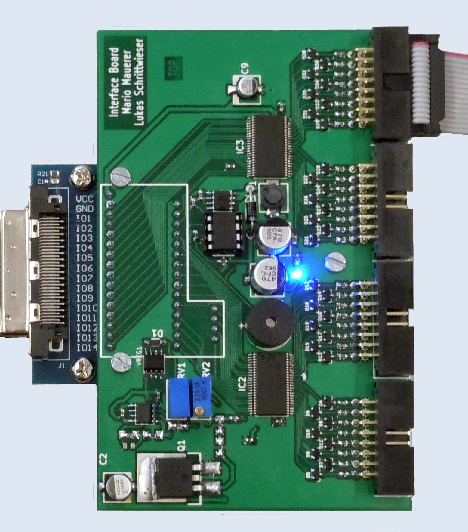
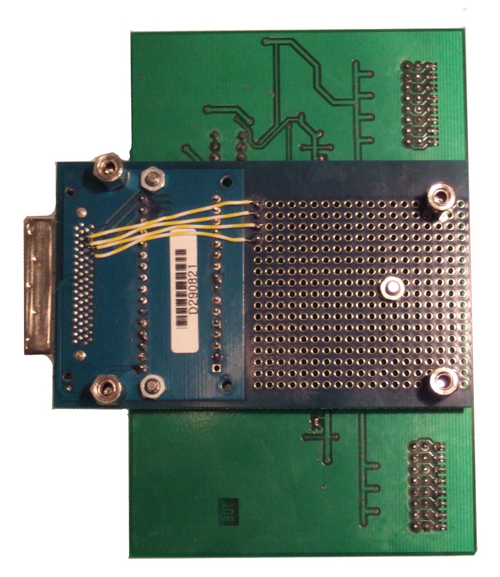
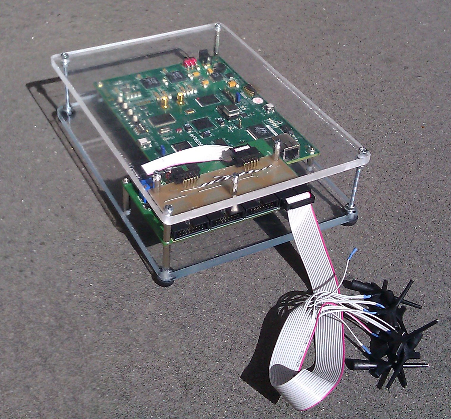
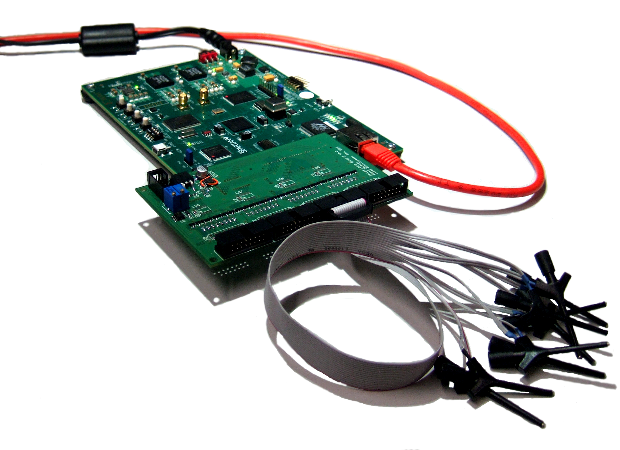
The following pictures show the Atlys-BitHound with the Interface Board.
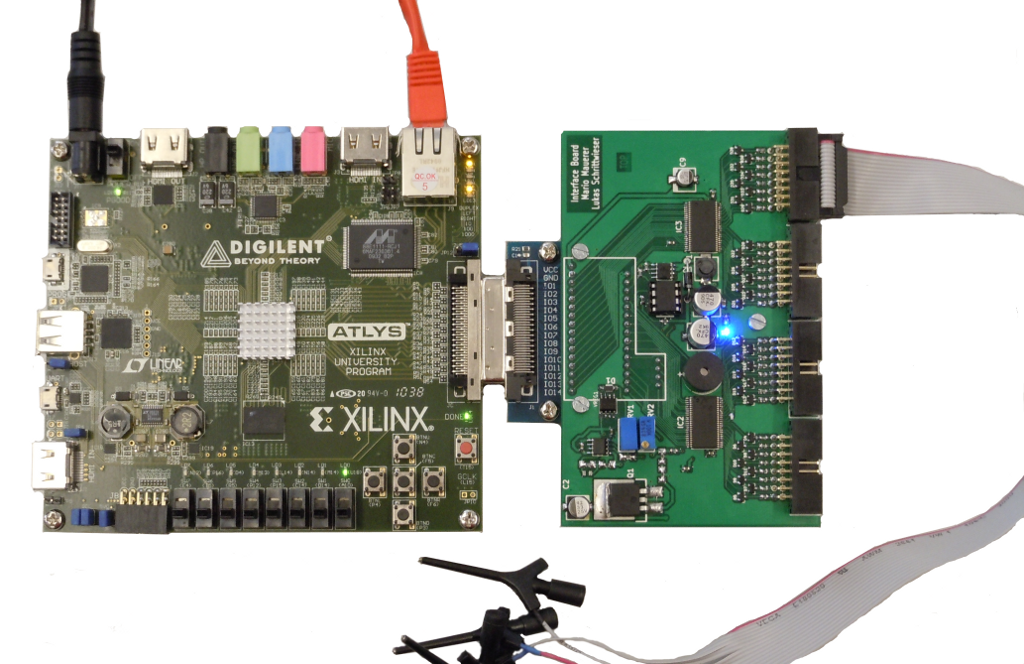
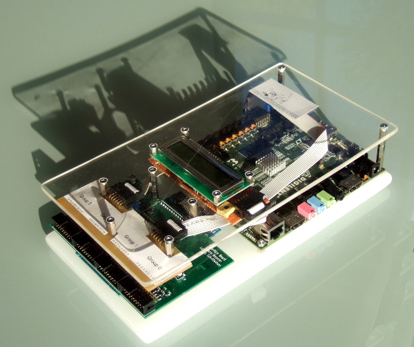
The following pictures show the Atlys-BitHound as it participated in the global finals of the "Digilent Design Contest 2011" (V2.0) - it has a case now. The LCD displays the IP-Adress and the LEDs on the front quickly show the status of each channel (low or high)(they shine through the PCB).
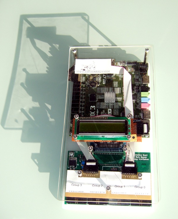
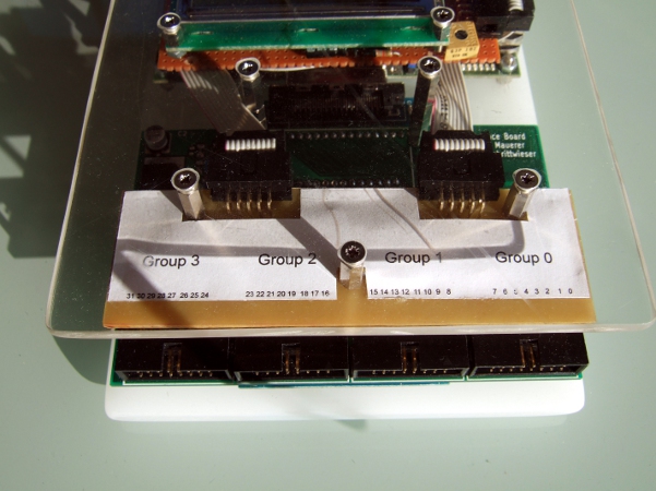
The interface Board is soldered ontop of a Digilent VMODWW extension board. However, this interface board is not necessary for the logic analyzer to work, it just provides an easy interface for the probes, a wide voltage range and it has an overvoltage protection.
Version 2.1
Improvements over V2.0:
Fixed a bug that caused a firmware deadlock
Implemented a lossless LZRW1 data compressor core to speed up sample transfer between BitHound and the PC (~double speed).
An serial port analyzer tool was added. You can now decode RS232 style serial communication and check for various problems (like baud rate mismatch, stop bit problems etc)
BitHound_ATLYS_2.1.zip
The following pdf file (BitHound_manual_V2.0) is a rough manual of the BitHound V2.0. It shortly explains how to use it.
BitHound_manual_V2.1.pdf
The following .zip only contains the PC-client for Windows and Linux. (intended for the Bastli electronics lab - when just the client is needed on a personal computer)
PC-client_V2.1.zip
Version 2.0
Improvements over V1.0:
Completely redesigned trigger, easier trigger-configuration in the GUI, adapted AVR-firmware (FPGA softcore), enhanced LCD and Channel-LED-support.
You can find the complete project in the following .zip-file (BitHound_ATLYS_2.0_.zip). The schematics for the interface board have been created with Kicad. Xilinx ISE 12.3 has been used for the FPGA-part in Version 2.0. You will also find a complete documentation of the project in the .zip.
BitHound_ATLYS_2.0_.zip
The following pdf file (BitHound_manual_V2.0) is a rough manual of the BitHound V2.0. It shortly explains how to use it.
BitHound_manual_V2.0.pdf
Version 1.0 (not recommended for new designs!)
You can find the complete project in the following .zip-file (BitHound_ATLYS_1.0_.zip). The schematics for the interface board have been created with Kicad. Xilinx ISE 12.3 has been used for the FPGA-part in Version 1.0. You will also find a complete documentation of the project in the .zip.
BitHound_ATLYS_1.0_.zip
The following pdf file (BitHound_manual) is a rough manual of the BitHound V1.0. It explains how to use it.
BitHound_manual.pdf
The following .zip only contains the PC-client for Windows and Linux. (intended for the Bastli electronics lab - when just the client is needed on a personal computer)
PC-client.zip
The following (not so serious ;-) ) video quickly presents the ATLYS-BitHound:
Xilinx SP601 Version
Note that this version is no longer improved and enhanced.
This Version of BitHound is based on the SP601 board from Xilinx.
The following picture shows the SP601-BitHound with and without an enclosure.
To connect the circuit you want to analyze to the FPGA, an interface-board that can be attached to the SP601 has been designed.
It provides an overvoltage protection to protect the FPGA as well as level shifters. With this board, it is possible to analyze circuit operation between 2.5V and 5V.
However, this interface board is not essential for the logic analyzer to work, it just provides a simple interface for the probes and it protects the FPGA-board.
Note the brown colored PCB in the left picture - it has got four 74HC595 shiftregisters and 32 LEDs on it which are controlled via the SPI-Interface. The LEDs represent the logic state of each channel and give a quick overview of the channel states.
You can find the complete project in the following .zip-file (BitHound_SP601_1.0_.zip). The schematics have been created with Altium designer. Xilinx ISE 12.3 has been used for the FPGA-part. You will also find a complete documentation of the project in the .zip.